Skip to content
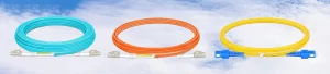
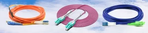
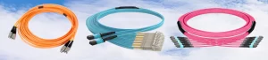
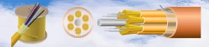
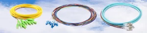

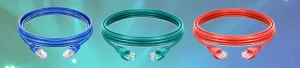





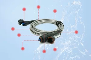
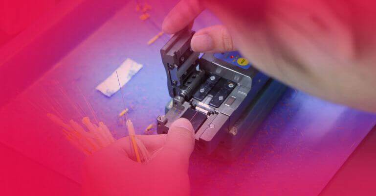





Fiber optic patch cords are crucial components in modern data transmission networks, and their performance is largely determined by insertion loss (IL) and return loss (RL). In this article, we provide an in-depth explanation of these two key tests, their significance, testing procedures, industry standards, and how FiberMania ensures quality through our rigorous testing and sampling processes.
1. Concepts and Importance
1.1 Insertion Loss (IL)
Insertion Loss is the reduction in optical power as light passes through a fiber optic connection, measured in decibels (dB). It reflects the efficiency of the patch cord in transmitting optical signals. Low IL is critical for maintaining signal strength across long distances and ensuring high-speed data integrity.
1.2 Return Loss (RL)
Return Loss measures the amount of light reflected back toward the source due to discontinuities or imperfections at the connector interface. Higher RL (larger dB values) indicates lower reflection, which is essential for preventing signal degradation, especially in high-speed single-mode networks.
Importance:
-
IL directly affects signal power and transmission distance.
-
RL affects network stability and minimizes noise and back-reflection.
2. Testing Objectives
Fiber optic patch cord tests aim to:
-
Verify that IL and RL meet international standards.
-
Ensure compatibility with network equipment.
-
Guarantee stable performance for different types of optical fibers (single-mode or multimode).
3. Testing Standards
Fiber optic testing follows international standards, mainly:
| Standard | Description |
|---|---|
| IEC 61753-1 | Defines optical connector performance and test methods. |
| IEC 61300-3-4 | Standard for IL testing of connectors. |
| IEC 61300-3-6 | Standard for RL testing using appropriate light sources. |
| TIA/EIA-568-C.3 | Defines performance limits for fiber patch cords, including IL and RL. |
4. Test Equipment
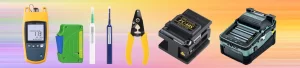
Common instruments used include:
-
Optical Power Meter (OPM): Measures transmitted optical power.
-
Light Source (LS): Provides stable light at defined wavelengths (e.g., 1310 nm, 1550 nm for single-mode; 850 nm, 1300 nm for multimode).
-
Optical Loss Test Set (OLTS): Integrates LS and OPM for IL measurement.
-
Optical Return Loss Meter / OTDR (Optical Time Domain Reflectometer): Measures back-reflected light for RL.
5. Testing Procedures
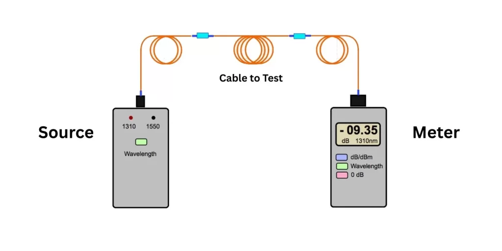
5.1 Insertion Loss Testing
-
Connect the light source to one end of the patch cord.
-
Connect the optical power meter to the other end.
-
Measure the output power and calculate IL using the formula:
IL (dB) = 10 × log10(P_in / P_out) -
Repeat measurements for multiple wavelengths if required.
-
Compare results against the standard limits.
5.2 Return Loss Testing
-
Connect the patch cord to an RL meter or OTDR.
-
Inject light at the specified wavelength.
-
Measure reflected power returned to the source.
-
RL is expressed in dB; higher values indicate better performance.
-
Repeat for different wavelengths and average the readings.
6. IL and RL Standards for Different Fiber Types
| Fiber Type | Typical IL (dB) | Typical RL (dB) | Notes |
|---|---|---|---|
| Single Mode (OS2) | ≤0.3 dB | ≥50 dB | High-speed, long-distance applications; very sensitive to reflections |
| Multimode OM1/OM2 | ≤0.5 dB | ≥30 dB | Short-distance, less sensitive to RL |
| Multimode OM3/OM4/OM5 | ≤0.3 dB | ≥30 dB | High-speed multimode networks; IL critical for 10G+ links |

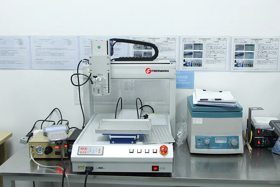
7. FiberMania’s Testing and Sampling Workflow
Incoming Inspection: Random samples from production batches are inspected for connector quality and visual defects.
Insertion Loss & Return Loss Testing: Using calibrated OLTS and RL meters, each sample is tested per IEC/TIA standards.
Environmental Stress Tests: Temperature and bend tests ensure IL and RL remain within limits under real-world conditions.
Data Recording and QC Approval: Test results are logged in FiberMania’s QC system, with batches approved only if all samples meet specifications.
Random Batch Sampling: Continuous quality monitoring is conducted by selecting additional units at random intervals during production.
This ensures every fiber optic patch cord leaving FiberMania meets rigorous performance standards for IL and RL.
8. Additional Considerations
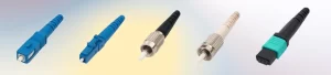
Connector Types: LC, SC, FC, ST, MPO/MTP affect IL and RL values.
Polishing Methods: UPC (Ultra Physical Contact) vs APC (Angled Physical Contact) connectors influence return loss (APC generally ≥60 dB).
Cabling Environment: Handling, bending, and installation impact IL; protective booting and proper routing reduce stress.
Conclusion
Insertion loss and return loss are two critical optical parameters that determine the performance of fiber optic patch cords. Adhering to international standards and conducting rigorous testing ensures signal integrity, network stability, and long-term reliability. FiberMania integrates these testing practices with comprehensive OEM/ODM quality control to deliver high-performance fiber patch cords for global customers.