Skip to content













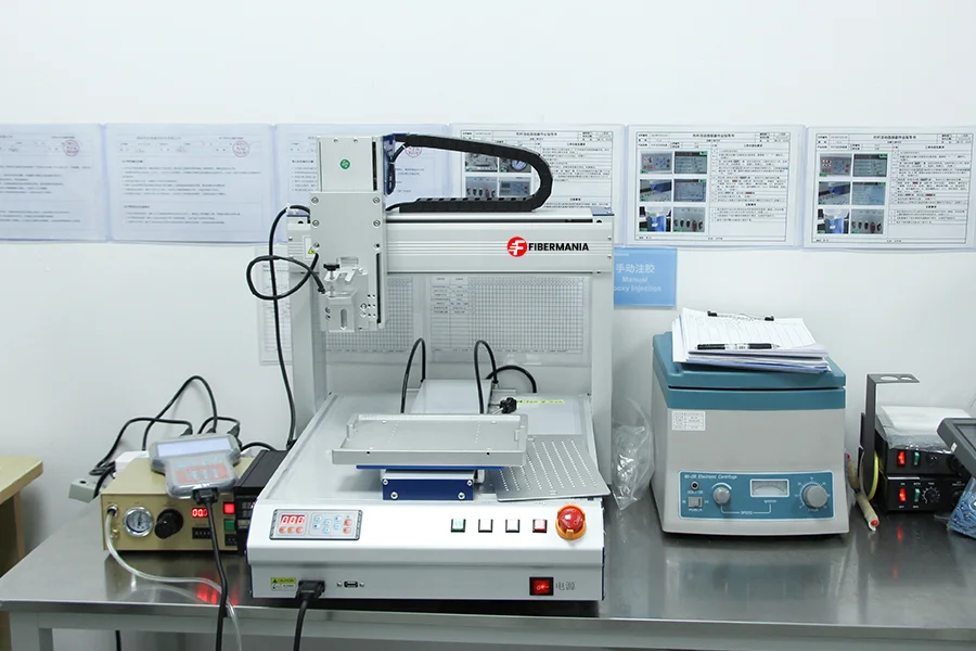



Fiber optic splice enclosures protect fiber splices and cable connections from moisture, dust, mechanical stress, and other environmental hazards in outdoor networks. Among the most common designs, dome and inline fiber optic splice enclosures serve similar protection purposes but differ in housing structure, cable-entry arrangement, maintenance access, and suitability for particular installation environments.
Choosing between them is not simply a matter of selecting a vertical or horizontal housing. The better option depends on how cables enter the enclosure, where the splice point is installed, how many branch cables are required, whether mid-span access is necessary, and how technicians will maintain the network over time.
This guide compares dome and inline fiber optic splice enclosures, explains their common features and differences, and explores practical deployment scenarios to help network planners, contractors, and fiber optic equipment buyers make the right choice.
1. What Are Dome and Inline Fiber Optic Splice Enclosures?
Dome and inline enclosures are designed to protect fusion splices and manage fiber slack at outdoor connection points. Both can be used in fiber-to-the-home (FTTH) networks, telecommunications infrastructure, access networks, and other outdoor fiber installations. Their main difference lies in the housing design and the way cable entries are arranged.
Dome Fiber Optic Splice Enclosures
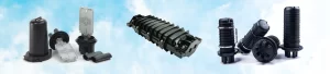
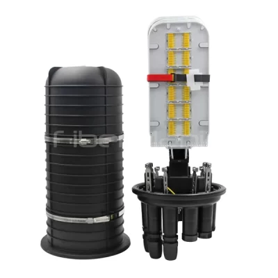
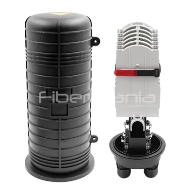
A dome fiber optic splice enclosure typically consists of a removable dome-shaped cover and a base that accommodates cable-entry ports, sealing components, and internal splice trays. The dome can be removed to access the splice trays, depending on the model’s opening and re-entry procedure.
Because cable entries are generally concentrated at the base, this design can accommodate multiple incoming and outgoing cables within a relatively compact footprint. Some models also support express cable entry, splitter installation, or dedicated branch configurations.
Dome enclosures are frequently considered for distribution points where a feeder cable connects to several branch cables, particularly in underground access networks and FTTH deployments.
Inline Fiber Optic Splice Enclosures
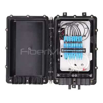
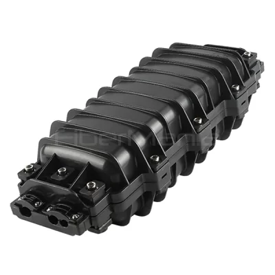
An inline fiber optic splice enclosure, also called a horizontal splice closure, usually has an elongated housing with cable-entry ports arranged at opposite ends, along the sides, or in another model-specific configuration.
This layout is convenient when cables approach a splice point from different directions. The enclosure can accommodate straight-through splicing, cable branching, and certain mid-span access arrangements when its ports, seals, and internal fiber-management system support those configurations.
Inline enclosures are commonly considered for linear cable routes, including buried distribution cables, aerial fiber routes, and backbone or access network joints.
Neither design is restricted to one network topology. The actual number of cables, permitted entry arrangements, splice capacity, and installation orientation must be confirmed for the selected model.
2. Dome vs. Inline: What Are the Main Differences?
Although both enclosure types protect fiber splices, their physical designs influence how they fit into an installation.
| Comparison factor | Dome Fiber Optic Splice Enclosure | Inline Fiber Optic Splice Enclosure |
|---|---|---|
| Housing design | Dome-shaped cover and base | Elongated horizontal housing |
| Typical cable entry | Multiple entries concentrated around the base | Entries commonly arranged at opposing ends or along the housing |
| Common deployment consideration | Multiple feeder and branch cables entering a compact node | Cables following a linear route through a splice point |
| Installation space | Requires sufficient room around the base and clearance to remove the dome | Requires space along the housing and adequate cable-bend clearance at the entries |
| Branch connections | Depends on available ports, seals, and internal routing | Depends on available ports, seals, and internal routing |
| Mid-span access | Available on models specifically designed for express or uncut-cable entry | Available on models specifically designed for express or uncut-cable entry |
| Splice capacity | Model- and tray-dependent | Model- and tray-dependent |
| Waterproof performance | Determined by the tested enclosure and sealing configuration | Determined by the tested enclosure and sealing configuration |
| Maintenance | Depends on cover removal, tray access, and resealing procedures | Depends on housing opening, tray access, and resealing procedures |
The most important distinction is cable-entry geometry rather than an absolute difference in functionality. A dome enclosure is not automatically better for branching, and an inline enclosure is not limited to straight-through splicing.
Likewise, a larger enclosure does not necessarily offer better protection. The correct selection must account for the cable construction, entry-seal range, environmental exposure, internal fiber arrangement, and required maintenance access.
3. Where Are Dome and Inline Enclosures Used?
The best way to compare these two enclosure types is to examine how they perform in real deployment scenarios.
Scenario 1: FTTH Distribution Nodes With Multiple Branch Cables
In an FTTH access network, a feeder cable may reach a distribution point and connect to several distribution or drop cables serving nearby buildings and households.
A dome enclosure is often a practical starting point when multiple cables need to enter the same node from different directions. Its base-mounted entry arrangement can simplify cable grouping, provided the selected model has enough suitable ports and sufficient internal routing space.
An inline enclosure can also support this application if its entry configuration accommodates the feeder and branch cables without exceeding the available sealing positions or compromising fiber management.
What to check before choosing:
The number of feeder, distribution, and drop cables.
The available cable-entry ports and compatible sealing components.
Whether the enclosure supports the planned splice and branching arrangement.
Whether additional branch cables may be required during network expansion.
Recommended approach: Consider a dome enclosure for a compact distribution node with several branch cables entering around a common base. Choose an inline enclosure instead when the site layout and cable route are better suited to its housing geometry.
Scenario 2: Underground Handholes and Buried Cable Routes
Underground handholes are common locations for fiber splicing in urban access networks, campus networks, and telecommunications infrastructure. The enclosure may be installed where a buried cable continues along a route or where a local branch is created.
For a cable route running through a handhole from one side to the other, an inline enclosure may be easier to arrange along the cable path. Its elongated housing can fit naturally beside the cable, provided the handhole offers sufficient length and bend clearance.
A dome enclosure may be more suitable when several cables converge at one access point or when the network requires multiple branch connections within a limited footprint.
However, underground installation introduces requirements that housing shape alone cannot resolve. Handholes may accumulate standing water, experience seasonal flooding, or expose closures to soil movement and mechanical loads.
What to check before choosing:
Available handhole dimensions and mounting options.
Clearance for cable bends, entry seals, and closure opening.
The expected duration and severity of water exposure.
The specified ingress-protection rating and its applicable test conditions.
Cable-jacket compatibility with the selected sealing system.
Recommended approach: Start with inline for a relatively linear buried cable joint and consider dome for a multi-branch node. In either case, verify the exact closure and cable-sealing configuration against the site’s water-exposure requirements.
Scenario 3: Aerial Fiber Optic Networks on Poles or Along Roads
Aerial fiber routes often follow roads, utility poles, and building connections. Splice points may connect two sections of a main cable or distribute fibers into nearby branches.
An inline enclosure is frequently considered for these applications because its elongated body can follow the direction of the cable route. It may also simplify the arrangement of cable entries and strain-relief components when the enclosure is installed along an aerial span or pole-mounted cable path.
A dome enclosure can also be used for aerial applications when the model is approved for the intended mounting method and its dimensions, cable entries, and environmental ratings meet the project requirements.
The key issue is not whether the housing looks horizontal or vertical. It is whether the mounting hardware securely supports the enclosure, cable loads are properly managed, and the closure can be accessed safely for maintenance.
What to check before choosing:
Whether the model is approved for aerial or pole-mounted installation.
Mounting brackets and available attachment points.
Cable tension, strain relief, and bend-radius requirements.
Wind, temperature, UV exposure, and other site conditions.
The clearance required for opening and servicing the enclosure.
Recommended approach: Consider inline for splice points along a continuous aerial cable route. Select dome when its port layout and mounting arrangement better suit a branch-distribution point.
Scenario 4: Mid-Span Splicing Without Cutting the Main Cable
Some fiber network installations require technicians to access selected fibers in a main cable while leaving the cable itself uncut. This is known as mid-span access or express cable entry.
For example, a backbone cable may pass through several access points, but only a portion of its fibers needs to be spliced to local distribution cables at each point. Maintaining the continuity of the remaining fibers can reduce unnecessary disruption to the network.
Both dome and inline enclosures can support this arrangement, but only when the selected model is specifically designed for it. Certain closures provide an oval port or another dedicated entry arrangement for accommodating an uncut cable section.
The internal design must also provide sufficient room to store uncut buffer tubes and fiber slack without violating bend-radius limits or interfering with the splice trays.
What to check before choosing:
Whether the enclosure explicitly supports mid-span access.
The allowable cable diameter and compatible express-entry seal.
The number of uncut buffer tubes that can be accommodated.
The required storage space for uncut fibers and cable slack.
Whether the intended branch splices fit within the tray configuration.
Recommended approach: Select by verified mid-span capability first, then compare dome and inline geometry. Do not assume that either shape supports uncut-cable entry simply because it has sufficient splice capacity.
Scenario 5: FTTH Nodes With PLC Splitters
In passive optical network (PON) deployments, a fiber optic splice enclosure may serve as a location for a PLC splitter that distributes an optical signal to multiple subscribers.
For example, a feeder fiber may connect to a splitter, with the splitter outputs routed toward several distribution branches. In this case, the enclosure must support not only fiber splicing but also the required splitter mounting and fiber routing.
A dome enclosure may be worth considering when the project requires several cable entries around a central distribution point. An inline enclosure may also work if the specific model provides compatible splitter mounting and enough space for the incoming fiber, splitter, pigtails, and output routing.
It is important to distinguish among splice capacity, adapter positions, splitter outputs, and cable-entry ports. These are different specifications and cannot be substituted for one another.
What to check before choosing:
PLC splitter type, split ratio, dimensions, and mounting method.
Whether the splitter is spliced, connectorized, or supplied in a module.
Required adapter types and the number of adapter positions.
Fiber routing and slack-storage requirements.
The number of feeder and output cables.
Available space for future expansion and maintenance.
Recommended approach: Choose the enclosure that explicitly supports the intended splitter configuration. A dome design may be convenient for a compact branching node, but the actual internal accessories and available capacity should determine the final decision.
Scenario 6: Networks Requiring Frequent Maintenance or Future Expansion
Fiber networks change over time. New subscribers, additional distribution branches, repairs, and network upgrades may require technicians to reopen an enclosure and modify its internal connections.
A dome enclosure may provide convenient access to grouped splice trays when the installation has enough clearance to remove the cover. An inline enclosure may be easier to service when it is mounted along an accessible cable route and the housing can be opened without disturbing adjacent equipment.
Neither design is inherently easier to maintain in every situation. The opening mechanism, tray arrangement, available working space, and resealing procedure are more important than the housing category alone.
What to check before choosing:
How the housing opens and closes.
Whether splice trays can be accessed individually.
The time and tools required for re-entry.
Whether seals or other components must be replaced after opening.
The space required to handle the cover and fiber slack.
Spare tray capacity and room for future branch cables.
Recommended approach: Evaluate maintenance access at the actual installation site. If frequent re-entry is expected, request the manufacturer’s opening instructions and verify the complete resealing procedure before purchasing.
4. What Do Dome and Inline Enclosures Have in Common?
Despite their different shapes, dome and inline fiber optic splice enclosures share the same fundamental purpose: maintaining a protected and organized environment for fiber connections.
Both designs may provide the following features, depending on the model and supplied configuration.
Environmental protection. Both can protect fiber splices from moisture, dust, and external contamination when the housing, seals, cable entries, and installation procedures are appropriate for the environment.
Fiber splice management. Both may use splice trays to organize fusion splices, manage fiber slack, and separate connections. Tray capacity and the maximum supported splice count vary by product.
Cable retention and sealing. Both can incorporate cable-fixing components and entry seals to help protect fibers from cable movement and environmental exposure. The compatible cable diameters and sealing methods must be verified for the chosen configuration.
Straight-through and branching arrangements. Either design may support through connections and branch splicing when its port layout and internal routing permit the required arrangement. Outdoor network compatibility. Both are used in access, distribution, backbone, and other outdoor fiber networks, provided the product is approved for the intended environment and mounting method.
Maintenance and expansion. Both may be reopened for repair or network expansion, subject to the manufacturer’s re-entry and resealing procedures. The enclosure’s actual performance depends on its design and configuration, not simply on whether it is dome-shaped or inline.
5. How to Choose the Right Fiber Optic Splice Enclosure
Once the installation scenario is understood, use the following steps to narrow down the available options.
Step 1: Map the Cable Route
Determine whether the splice point lies on a continuous cable route or at a node where several cables converge.
For cables entering and leaving along a relatively straight route, start by evaluating inline designs.
For a node with multiple feeder and branch cables, evaluate dome designs with a suitable base-entry arrangement.
For complex branching or mid-span access, compare the exact port configuration and approved cable-entry methods.
These are starting points rather than absolute rules. Either enclosure type may work when the actual configuration meets the requirements.
Step 2: Calculate the Required Splice Capacity
Estimate the number of fusion splices needed at installation and the number likely to be required after future expansion.
Check the usable splice positions, tray capacity, fiber-slack storage, and the space required for uncut fibers. A closure advertised for 96 fibers, for example, should not automatically be assumed to accommodate every 96-fiber configuration or branching arrangement.
Confirm whether the manufacturer’s stated capacity refers to splice positions, supported fibers, or a particular tray configuration.
Step 3: Confirm Cable Entries and Outer Diameters
List every incoming and outgoing cable, including its construction and measured outer diameter (OD).
Verify the number of available ports, compatible seal ranges, cable-fixing components, and blanking plugs for unused entries. If an uncut main cable must pass through the closure, confirm the specific mid-span or express-entry arrangement.
A listed port count does not establish the allowable cable diameter or prove that every port can be used simultaneously in the planned configuration.
Step 4: Evaluate the Installation Environment
Consider whether the enclosure will be installed in a buried handhole, an aerial route, a pole-mounted distribution point, or another outdoor location.
Review the required ingress-protection rating, temperature range, UV exposure, mounting hardware, and mechanical conditions. Where immersion or standing water is expected, request evidence that the tested configuration meets the project’s required depth or pressure and duration.
Do not assume that dome enclosures are automatically more waterproof than inline enclosures, or that a stated IP rating guarantees suitability for every prolonged-immersion condition.
Step 5: Check Splitter and Connector Requirements
If the closure will accommodate a PLC splitter or connectorized outputs, confirm the exact splitter type, mounting accessories, adapter positions, connector interfaces, and internal routing.
Splice capacity, splitter output count, adapter count, and cable-entry count describe different functions. All must be checked independently.
Step 6: Plan for Maintenance and Expansion
Review how technicians will open the enclosure, access the trays, add branches, and restore the seals.
Allow for working clearance around the housing and cable entries. Check whether future work requires replacement sealing components and whether spare splice positions or tray space are available.
An enclosure that fits the initial splice count but cannot accommodate the planned expansion may increase maintenance costs later.
6. Final Comparison: Which One Should You Choose?
Use the following guide as an initial screening tool.
| Deployment requirement | Initial option to evaluate | Main reason |
|---|---|---|
| Straight-through joint along a buried cable route | Inline | Its elongated housing can align with the cable path |
| Aerial splice point along a continuous cable route | Inline | Its geometry may suit a linear cable arrangement |
| FTTH node with several branch cables | Dome | Multiple base entries may simplify cable grouping |
| Compact underground distribution node | Dome | The base-entry layout may suit a concentrated cable group |
| Mid-span access without cutting the main cable | Either, if specifically supported | Dedicated express-entry capability is essential |
| PLC splitter distribution point | Either, if internally compatible | Splitter mounting and output routing determine suitability |
| Installation with frequent re-entry | Either, based on service access | Opening and resealing procedures matter more than shape |
| Site exposed to standing water or immersion | Either, with verified specifications | Tested sealing performance and installation conditions are decisive |
The final choice should always be based on the complete product configuration, installation requirements, and expected network lifecycle.
Conclusion
Dome and inline fiber optic splice enclosures provide the same essential function: protecting and organizing fiber connections in outdoor networks. Their main differences lie in housing geometry, cable-entry arrangement, installation clearance, and access for maintenance.
For a splice point along a relatively straight cable route, an inline enclosure is a useful starting point. For a compact node with multiple feeder and branch cables, a dome enclosure may be more convenient. For mid-span access, PLC splitter integration, or demanding water exposure, however, the selected model’s verified specifications should take priority over its housing style.
By matching the enclosure to the cable route, splice requirements, site conditions, and future maintenance plan, network designers and installers can make a more reliable choice for long-term fiber infrastructure deployment.
Frequently Asked Questions
Is a dome fiber optic splice enclosure better than an inline enclosure?
Neither type is universally better. Dome enclosures are often considered for compact distribution nodes with multiple cable entries, while inline enclosures are often considered for splice points along continuous cable routes. The correct choice depends on port configuration, internal capacity, installation space, environmental conditions, and maintenance requirements.
Can an inline enclosure be used for FTTH branching?
Yes. An inline enclosure can support FTTH branching when its entry ports, sealing components, splice trays, and fiber-routing arrangement are suitable for the planned feeder and branch cables.
Are dome enclosures always more waterproof?
No. Waterproof performance depends on the enclosure design, seals, cable-entry configuration, installation procedure, and applicable test conditions. Compare the specifications and supporting test evidence for the exact product rather than relying on housing shape.
Can both types accommodate PLC splitters?
Some models of both types can accommodate PLC splitters. Confirm the available mounting accessories, splitter dimensions, adapter positions, splice capacity, and output routing before selecting an enclosure.
What information should be provided when requesting a quotation?
Provide the installation location, cable route, number and outer diameter of each cable, required splice capacity, branch count, mid-span access requirements, splitter or connector specifications, environmental exposure, mounting method, and expected maintenance needs. This information allows the supplier to recommend a suitable model and confirm the required accessories.