Skip to content
































A backbone network is the high-capacity infrastructure that connects major network segments, buildings, data centers, access networks, and other critical nodes. As enterprise networks, cloud computing, data centers, and digital services continue to generate increasing amounts of traffic, the backbone has become one of the most important parts of modern network infrastructure.
However, building a backbone network is not simply a matter of installing high-speed switches and connecting them with fiber optic cables. The physical transmission medium, optical transceivers, fiber distribution equipment, network topology, link budget, redundancy, and future capacity all need to be considered as part of a complete system.
This is particularly important for fiber optic backbone networks. Fiber provides the bandwidth and transmission distance required by modern high-speed networks, but the final performance of a backbone depends on how the fiber infrastructure and active equipment are designed together. A network that performs well when first installed may become difficult to expand or maintain if the original design does not account for future bandwidth growth, spare fiber capacity, or physical redundancy.
What Should Be Considered Before Designing a Backbone Network?
The first step in backbone network design is to understand what the network needs to connect and how much traffic it is expected to carry. A backbone connecting several office buildings on a corporate campus has very different requirements from a backbone interconnecting multiple data centers or carrier network nodes.
Transmission distance, current bandwidth, expected traffic growth, network topology, environmental conditions, equipment compatibility, and reliability requirements all influence the design. The physical installation environment is equally important. A backbone installed inside a data center can be managed very differently from one that runs between buildings, through underground ducts, or through outdoor communication cabinets.
A useful starting point is to establish the main design parameters before selecting individual components.
| Design Factor | Typical Consideration |
|---|---|
| Transmission speed | 10G, 25G, 40G, 100G, 400G, 800G or higher |
| Transmission distance | From short data center links to long-distance campus or carrier links |
| Fiber type | Single-mode or multimode |
| Fiber count | Based on current connections, redundancy, and future expansion |
| Topology | Point-to-point, ring, dual-path, or other redundant architecture |
| Optical budget | Fiber attenuation, connector loss, splice loss, and equipment specifications |
| Environment | Indoor, outdoor, underground, campus, data center, etc. |
| Reliability | Required level of link and equipment redundancy |
| Future expansion | Expected bandwidth, additional buildings, users, or network services |
The purpose of this planning stage is not to determine every product in advance. Instead, it establishes the technical boundaries within which the appropriate cables, transceivers, patch panels, and other components can be selected.
Why Is Fiber Optic Cable the Foundation of Modern Backbone Networks?
Fiber optic cable has become the primary physical medium for high-capacity backbone networks because it combines high bandwidth, long transmission distance, low attenuation, and immunity to electromagnetic interference.
As network traffic increases, the limitations of copper become more apparent. Copper Ethernet remains highly useful for short-distance connections, particularly at the access layer, but backbone links frequently need to carry traffic over longer distances and at much higher capacities. Fiber provides a much more practical foundation for these requirements.
Another important advantage is the ability to support high-density connectivity. A single fiber trunk cable can contain many individual fibers, allowing multiple backbone links to share the same physical cable pathway. This is particularly useful in data centers, telecommunications facilities, and large enterprise campuses where hundreds or thousands of optical connections may eventually be required.
Fiber also provides an effective foundation for future network upgrades. The physical fiber cable can often remain in place while the network equipment and optical transceivers are upgraded to higher data rates. This means that a properly planned fiber infrastructure can have a much longer service life than the active equipment connected to it.
For this reason, backbone design should generally begin with the physical fiber infrastructure rather than treating the cable as an afterthought to the selection of switches and transceivers.
How to Choose the Right Fiber for a Backbone Network
One of the most important decisions is whether to deploy single-mode or multimode fiber.
Single-mode fiber is generally preferred when the backbone needs to support long transmission distances, flexible wavelength options, or future expansion toward higher-speed optical technologies. Common single-mode fiber specifications include OS2 and ITU-T G.652.D, while G.657 fiber can be useful in applications where improved bend performance is important.
Single-mode fiber is widely used in campus backbones, telecommunications networks, metropolitan connections, data center interconnects, and other applications where transmission distance can extend beyond the practical range of multimode solutions.
Multimode fiber, including OM3, OM4, and OM5, is more commonly associated with shorter-distance high-speed connections. It is particularly useful inside data centers and enterprise facilities where network devices are located relatively close together. When the transmission distance falls within the supported range of the selected multimode transceiver, multimode fiber can provide an efficient and economical solution.
The choice between the two should therefore be based on the complete link rather than on fiber type alone.
| Fiber Type | Typical Backbone Application | Main Advantage |
|---|---|---|
| OS2 Single-Mode | Campus, telecom, long-distance, data center interconnect | Long transmission distance and broad application range |
| G.652.D Single-Mode | Telecom and backbone infrastructure | Standardized long-distance transmission |
| G.657 Single-Mode | Dense routing and space-constrained installations | Improved bend performance |
| OM3 Multimode | Data centers and enterprise networks | Cost-effective short-distance high-speed transmission |
| OM4 Multimode | High-speed data center backbone | Higher bandwidth-distance capability than OM3 |
| OM5 Multimode | Specific short-distance high-speed applications | Designed for wideband multimode applications |
For a new backbone that is expected to remain in service for many years, the decision should also consider future transmission speeds. Installing a fiber type that satisfies today’s requirements but limits tomorrow’s upgrade options can ultimately cost more than deploying a more flexible infrastructure from the beginning.
What Components Are Used in a Fiber Optic Backbone?
A fiber backbone consists of much more than the cable itself. The cable provides the physical transmission path, but a practical network also requires equipment for optical conversion, termination, connection, protection, and management.
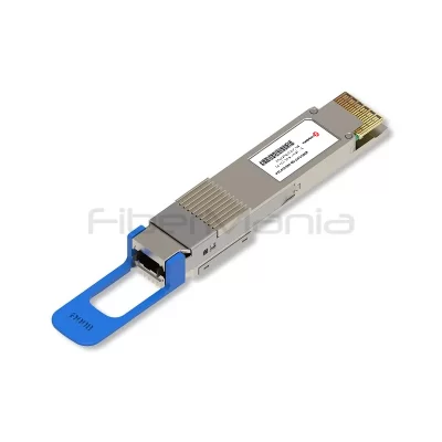
At the active layer, optical transceivers convert electrical signals from switches or routers into optical signals that can travel through the fiber. The appropriate transceiver depends on transmission speed, wavelength, distance, fiber type, connector interface, and the specifications of the network equipment.
For example, 100G backbone connections may use QSFP28 optical transceivers, while higher-capacity data center networks can use 400G QSFP-DD or 800G OSFP-based solutions. As data rates continue to increase, the relationship between the optical transceiver and the underlying fiber infrastructure becomes increasingly important.
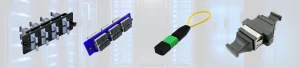
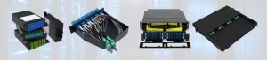
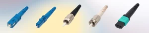
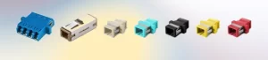
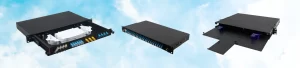
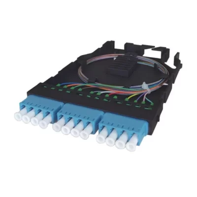
At the passive layer, fiber patch panels and Optical Distribution Frames provide structured termination and cross-connection. Instead of connecting backbone cables directly to active equipment, the fibers can be terminated at an organized distribution point. This makes it easier to identify individual fibers, perform testing, replace equipment, and introduce future connections without disturbing the entire cable system.
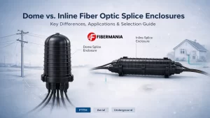
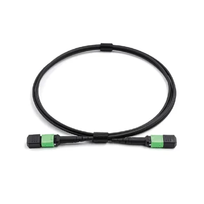
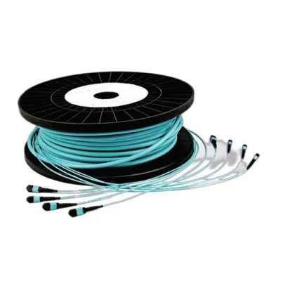
High-density applications may also use MTP/MPO trunk cables and corresponding patching systems. These solutions allow many fibers to be installed and connected efficiently within a relatively small physical space. In larger backbone installations, fiber splice trays, splice closures, and fiber enclosures are used where cables need to be spliced or protected, particularly in outdoor and building-to-building deployments.

How Should the Backbone Architecture Be Designed?
The physical and logical architecture of a backbone determines how traffic moves through the network and how the network responds when a connection fails.
A simple point-to-point backbone may be sufficient when two locations need a dedicated connection. For example, a company may use a pair of optical links to connect an office building directly to a central data center. This architecture is straightforward, but a single physical link failure can interrupt communication unless another path is available.
As the number and importance of network locations increase, redundant architectures become more attractive. A ring architecture provides an alternative route around the network, while a dual-homed architecture can connect an important network location to two separate core devices or paths.
In a large enterprise campus, for example, several buildings may connect to a central core through redundant fiber paths. In a data center, redundant connections between leaf and spine or core switching layers can provide continued connectivity when individual links or devices fail.
The appropriate architecture depends on the network’s availability requirements. There is little value in creating a theoretically redundant design if both supposedly independent links run through the same physical conduit. For critical networks, logical redundancy should be supported by physical path diversity wherever practical.
How to Plan Backbone Capacity and Future Expansion
Bandwidth planning is one of the areas where a short-term approach can create long-term problems.
A backbone should not be designed solely around the traffic generated by the network today. Data consumption tends to increase as organizations introduce cloud applications, video services, virtualization, AI workloads, high-performance computing, and other bandwidth-intensive applications.
For example, a building may initially require only a 10G connection to the core network. After several years, that same building could require 25G, 40G, or 100G connectivity. If the original physical infrastructure has no spare fibers or insufficient pathway capacity, upgrading the network may require new cable installation.
A better strategy is to distinguish between current active capacity and future physical capacity.
A backbone cable does not need to use every fiber immediately. Installing a higher-count fiber trunk can provide spare fibers that remain unused until they are needed. Similarly, patch panels and racks can be designed with additional capacity for future connections.
This is particularly valuable in difficult installation environments. Installing additional fiber during the original construction is often considerably easier than adding new cables later through occupied conduits, underground ducts, or finished buildings.
Future capacity planning should therefore consider not only the next equipment upgrade but also the expected growth of the entire network.
Why Redundancy and Physical Path Diversity Matter
Because the backbone aggregates traffic from multiple network segments, a backbone failure can affect a much larger area than an access-layer failure.
Redundancy is therefore one of the fundamental principles of backbone design. However, redundancy should be considered at several levels rather than simply adding a second connection.
At the equipment level, critical networks may use redundant core switches or routers. At the link level, multiple optical connections can provide alternative paths. At the physical level, independent fiber routes can protect the network from cable cuts, construction accidents, fire, or other pathway-related failures.
Consider a building connected to a data center by two fiber cables. If both cables pass through the same underground duct, a single excavation accident could cut both links simultaneously. From a logical perspective, the network has two links, but from a physical perspective, it still has a single point of failure.
For high-availability backbone networks, physical path diversity is therefore just as important as logical redundancy.
Fiber Management and Deployment Considerations
The quality of the backbone is not determined only by optical specifications. Physical installation and fiber management have a direct impact on long-term reliability.
Fiber cables must be routed within their specified bend radius and protected against excessive pulling force, crushing, sharp bends, and repeated mechanical stress. These issues may not immediately cause a complete link failure, but they can increase attenuation or create intermittent problems that are difficult to diagnose.
Fiber distribution equipment should also provide enough room for proper routing and future expansion. A patch panel that is completely filled during the initial installation may create significant difficulties when additional connections are required later.
Clear labeling is equally important. In a large backbone, technicians need to know where each cable originates, where it terminates, which patch panel and port it uses, and which network equipment it connects to. Proper documentation can significantly reduce troubleshooting time.
For large deployments, the fiber infrastructure should therefore be treated as a structured system rather than simply a collection of cables.
Common Backbone Network Design Problems
Many backbone problems originate from decisions made during the initial design rather than from failures of individual products.
One common problem is designing only for current bandwidth. A backbone may operate perfectly at 10G today but become difficult to upgrade when traffic reaches 25G or 100G. Without sufficient spare fibers, rack capacity, or cable pathway space, a relatively simple equipment upgrade can become a major infrastructure project.
Another problem is selecting the transceiver and fiber independently. Transmission speed, wavelength, fiber type, connector interface, and distance are interconnected parameters. A compatible solution must be evaluated as a complete optical link.
Ignoring the optical link budget is another frequent issue. A cable may appear suitable because its length is within the advertised transmission distance, but excessive connector or splice losses can reduce the available optical margin.
Redundancy is also sometimes misunderstood. Two logical connections do not necessarily provide two independent physical paths. If both cables share the same vulnerable route, a single physical incident can still disconnect both links.
Finally, poor fiber management can turn a technically sound backbone into a difficult network to maintain. Overcrowded cabinets, unclear labels, excessive fiber bending, and insufficient spare ports can increase the risk of human error and make future expansion more complicated.
How to Build a Future-Ready Backbone Network
A future-ready backbone does not necessarily require deploying the highest-speed equipment available today. Instead, the goal is to build physical infrastructure that can support multiple generations of active equipment.
Fiber is particularly well suited to this strategy because the cable infrastructure can remain in service while transceivers and switches are upgraded. A backbone that is physically designed for higher fiber counts, organized patching, and adequate pathway capacity can therefore support significant changes in network architecture without requiring a complete rebuild.
For example, a project may initially activate only a portion of the fibers in a high-count trunk cable. The remaining fibers can be reserved for future links, redundancy, or new network services. Similarly, an ODF or patch panel can be designed with additional ports so that new equipment can be connected without replacing the existing distribution infrastructure.
The same principle applies to transmission technology. When selecting fiber, connectors, patching systems, and cable assemblies, designers should consider not only today’s 10G or 100G requirements but also the potential migration toward 400G, 800G, and higher-speed architectures.
The most future-ready backbone is therefore not necessarily the one with the most expensive equipment. It is the one that provides sufficient physical capacity, organized infrastructure, optical margin, and upgrade flexibility.
Conclusion
A reliable fiber optic backbone network is built through a combination of appropriate fiber infrastructure, high-speed optical equipment, structured fiber management, sound network architecture, and careful capacity planning.
The first step is to understand the network’s transmission distance, bandwidth requirements, physical environment, and reliability objectives. From there, the appropriate fiber type can be selected, followed by optical transceivers, fiber trunk cables, patch panels, ODFs, patch cords, splice systems, and other supporting infrastructure.
For most modern backbone networks, the physical fiber infrastructure deserves particular attention because it often remains in service much longer than the active networking equipment. Providing sufficient fiber count, organized distribution, physical redundancy, and expansion capacity during the initial installation can significantly reduce the cost and complexity of future upgrades.
Ultimately, backbone network design should not focus only on achieving the required performance today. The objective is to create a stable and manageable infrastructure that can continue to support increasing bandwidth, new optical technologies, additional network nodes, and changing business requirements over many years.