Skip to content
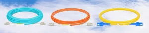


In the world of high-speed telecommunications, the difference between a high-performing network and a total system failure can be measured in nanometers. At the heart of this precision lies the art and science of fiber optic polishing. As we transition into an era of 800G networks and hyperscale data centers, understanding how we treat the microscopic ends of a glass fiber is more critical than ever.
1. The Genesis of Polishing: Why It Matters
Fiber optic communication relies on the transmission of light pulses through a glass core. However, when two fibers are joined together using connectors, the point of contact becomes a potential barrier. If the fiber ends are rough, uneven, or contaminated, the light will scatter, reflect, or be absorbed, leading to Insertion Loss (IL) and Return Loss (RL).
The Purpose of Polishing: Polishing is the process of finishing the end-face of a fiber optic connector to ensure optimal light transmission. The significance of this process cannot be overstated:
Physical Contact: It ensures that the glass cores of two mating fibers actually touch, eliminating air gaps.
Geometric Precision: It shapes the ceramic ferrule into a specific radius to ensure alignment.
Surface Integrity: It removes scratches and defects caused by the cleaving process.
Without high-quality polishing, modern high-speed internet would be impossible. High return loss (light reflecting back toward the source) can damage sensitive laser transmitters and introduce “noise” that degrades signal quality.
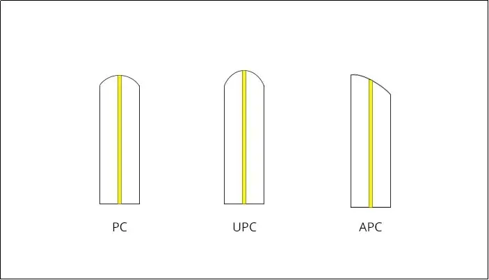
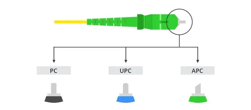
2. The Three Pillars: Comparing PC, UPC, and APC
Over the decades, three primary polishing styles have dominated the industry: Physical Contact (PC), Ultra Physical Contact (UPC), and Angled Physical Contact (APC). Each represents a step forward in engineering.
| Feature | PC (Physical Contact) | UPC (Ultra Physical Contact) | APC (Angled Physical Contact) |
| End-Face Geometry | Flat or slightly curved | Extended spherical radius | 8-degree angled surface |
| Typical Return Loss | ≥35dB | ≥50 to 55dB | ≥ 60 to 65 dB |
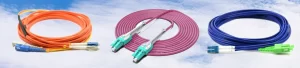
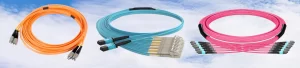
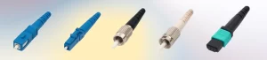
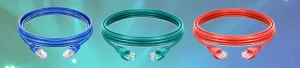
| Connector Color | Usually Black/Beige | Blue | Green |
| Best Use Case | Legacy low-speed systems | Digital TV, Enterprise, LAN | FTTH, PON, High-power lasers |
| Reflection Direction | Back into the core | Back into the core | Out into the cladding |
| Cost/Complexity | Low | Medium | High |
Deep Dive into the Comparison
PC Polishing was the original standard. By curving the ferrule slightly, it forced the cores to touch. However, the surface finish was relatively rough by today’s standards.
UPC Polishing is an evolution of PC. It uses an extended polishing cycle and finer abrasive films to achieve a “super-polished” finish. This creates a much better contact area and significantly lower return loss than standard PC.
APC Polishing is the most sophisticated. By polishing the end-face at a precise 8-degree angle, any light that reflects at the connection point is not sent back toward the source; instead, the angle forces the reflected light to leak out into the fiber’s cladding. This is why APC is mandatory for high-power systems like CATV and GPON.
3. The Decline of PC: Why the Industry is Moving On
If you look at modern data center specifications or telecom tenders, PC (Physical Contact) polishing is almost entirely absent. The industry has effectively “fired” the standard PC polish in favor of UPC and APC. But why?
A. The Speed Barrier
Standard PC polishing typically offers a return loss of about 35dB. In the era of 10Mbps or 100Mbps Ethernet, this was acceptable. However, as we moved to 10G, 40G, and now 400G/800G, the sensitivity of the transceivers increased. High reflections (low return loss) from a PC connector cause Bit Error Rates (BER) to spike, making the connection unstable.
B. The Laser Sensitivity Factor
Modern networks use sophisticated lasers (like DFB lasers) that are extremely sensitive to back-reflections. PC connectors allow too much light to bounce back into the laser cavity, which can cause laser instability and even permanent hardware damage.
C. Manufacturing Standardization
The cost difference between manufacturing a PC connector and a UPC connector has shrunk to nearly zero thanks to automated polishing machines. Since UPC offers significantly better performance for a similar price, there is no longer a financial or technical justification for maintaining PC inventory.
4. Technical Innovations: The Future of Polishing
The fiber optic industry is not static. As we look toward the future, the way we terminate and polish fibers is undergoing a radical transformation.
I. Automated 3D Interferometry
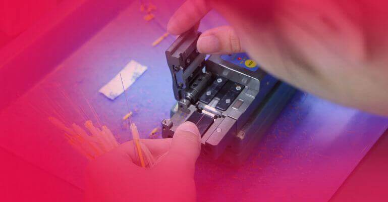
In the past, polishing quality was checked via a simple microscope. Today, innovation lies in Non-contact 3D Interferometry. This technology measures the ferrule’s radius of curvature, apex offset (how centered the polish is), and fiber undercut/protrusion at a sub-micron level. The next step is AI-integrated testing, where the machine automatically adjusts the polishing pressure based on real-time surface analysis.
II. Laser Polishing & Non-Contact Termination
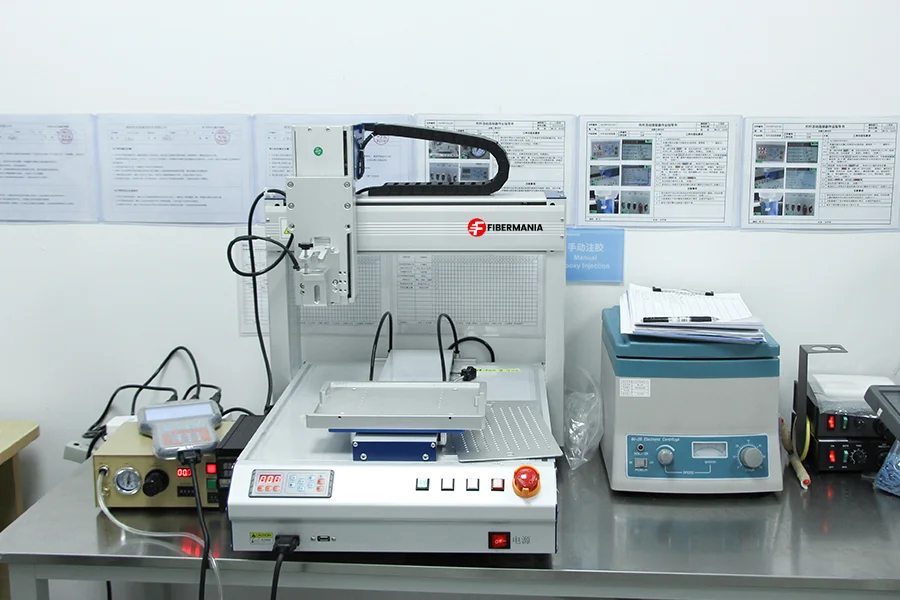
One of the most exciting innovations is Laser Cleaving and Polishing. Traditional polishing uses physical abrasive films (diamond, silicon carbide) and water. This creates physical stress on the glass. New laser systems can “fire-polish” the fiber end-face, creating a perfectly smooth surface in seconds without any physical contact. This eliminates the risk of “pitting” or “scratches” and significantly increases production speed for B2B factories like FiberMania.
III. Expanded Beam (EB) Technology
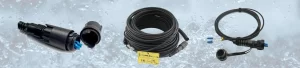
While not a “polishing” technique in the traditional sense, Expanded Beam technology is an innovation aimed at replacing the need for ultra-precise polishing in harsh environments. By using a lens to expand the light beam across the connection point and then refocusing it into the receiving fiber, the system becomes less sensitive to the microscopic surface defects that traditional polishing seeks to fix.
IV. Nano-Abrasive Films
Future innovation in mechanical polishing involves the development of Nano-engineered Abrasive Films. These films use molecular-level grain structures to provide a “mirror finish” that exceeds current UPC standards, pushing return loss toward the 60dB mark without requiring the 8-degree angle of an APC connector.
Conclusion: The Precision Imperative
Fiber optic polishing has evolved from a manual craft into a high-precision manufacturing science. From the early days of flat PC connectors to the sophisticated 8-degree APC geometry and the future of laser fire-polishing, the goal remains the same: maximum light, minimum reflection.
For B2B partners and network integrators, choosing the right polishing type is no longer just a technical detail—it is a strategic decision. As FiberMania continues to lead in the OEM/ODM production of MPO/MTP and SC/LC assemblies, we remain committed to implementing the latest innovations in polishing technology. Whether it is supporting the migration to 800G or ensuring the reliability of FTTH networks, the future of connectivity is clear, polished, and bright.