Skip to content


The data center industry is currently standing on the precipice of a monumental shift. As Artificial Intelligence (AI) and Machine Learning (ML) clusters scale to tens of thousands of GPUs, the demand for bandwidth has moved beyond the capabilities of 400G and even 800G systems. The industry is now racing toward the 1.6T (1.6 Terabit per second) standard.
However, reaching 1.6T is not as simple as adding more fiber or doubling the clock speed. It requires a fundamental rethinking of how we transmit data—from the digital signal processing (DSP) inside the module to the precision of the fiber optic patch cords connecting the racks.
1. The Core Engine: The Transition to Single-Lane 200G
The most significant architectural change in the move to 1.6T is the evolution of the electrical and optical lanes. While 800G modules typically use 8 lanes of 100G, 1.6T modules require 8 lanes of 200G.
The PAM4 Complexity
For years, the industry relied on NRZ (Non-Return to Zero) signaling. We then transitioned to PAM4 (4-Level Pulse Amplitude Modulation) to double the data rate without doubling the bandwidth. However, at 200G per lane, we are approaching the Shannon Limit—the theoretical maximum rate of error-free information transmission.
Signal-to-Noise Ratio (SNR) Degradation: In a PAM4 signal, the “eye” of the signal (the space where the receiver distinguishes between 0, 1, 2, and 3) becomes incredibly narrow. At 200G, the signal-to-noise ratio drops significantly.
The DSP Challenge: To recover these fragile signals, next-generation DSPs must employ incredibly complex algorithms. This creates a “Power Wall”—the more processing required to clean up the signal, the more heat the module generates.
2. Material Science: Beyond Traditional Silicon
As we push toward 200G lanes, the materials we’ve used for decades are hitting physical limits. To maintain signal integrity over fiber optic cables, the industry is exploring three primary pathways:
Thin-Film Lithium Niobate (TFLN)
TFLN is the “rising star” of the 1.6T era. Traditional Silicon Photonics (SiPh) modulators have high insertion loss and limited bandwidth. TFLN offers ultra-high bandwidth and low drive voltage, making it possible to achieve 200G speeds with significantly lower power consumption.
Indium Phosphide (InP)
A long-standing champion in high-end telecommunications, InP remains a strong contender for 1.6T due to its high efficiency in laser emission and modulation. However, its cost and scalability for high-volume data center applications remain a point of debate for OEM manufacturers.
3. The Physical Layer: Why “Good Enough” Cables Fail at 1.6T
This is where the theoretical meets the physical. As a provider of OEM/ODM fiber optic products, we see firsthand how the physical layer is becoming the most critical link in the 1.6T chain.
The Tyranny of Insertion Loss
At 200G per lane, the tolerance for signal loss is almost zero. In older 10G or 40G systems, a slightly dusty connector or a sub-par polish on a ferrule might cause a minor drop in performance. In a 1.6T environment, that same imperfection will cause a total link failure.
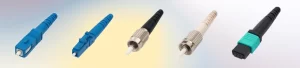
Ultra-Low Loss (ULL) Connectors: To support 1.6T, patch cords must utilize ULL connectors with insertion losses consistently below 0.1dB.
Return Loss (ORL): Back-reflections can destabilize the high-speed lasers in 1.6T modules. High-quality APC (Angled Physical Contact) polishing is becoming the standard to ensure reflections are directed into the cladding rather than back to the source.
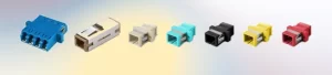
The Shift to Parallel Optics (MPO/MTP)
1.6T is driving a massive shift toward high-density cabling. We are seeing a move from simple LC duplex connectors to 16-fiber and 32-fiber MPO/MTP solutions. For an OEM manufacturer, the challenge lies in maintaining perfect alignment across all 16 or 32 fibers simultaneously—a feat of micrometer-scale engineering.

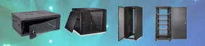
4. Power and Heat: The Silent Killers
A 1.6T pluggable module is expected to consume nearly 25 to 30 Watts. In a switch filled with 32 or 64 such modules, the thermal density is comparable to a small kitchen oven.
LPO (Linear Drive Pluggable Optics)
To combat this, the industry is looking at LPO. By removing the power-hungry DSP from the module and relying on the switch’s ASIC to handle the signal, power consumption can be cut by up to 50%. However, this puts even more pressure on the quality of the fiber optic cables. Without a DSP to “clean” the signal, the physical cable must be virtually perfect.
CPO (Co-Packaged Optics)
Looking further ahead, CPO brings the optical engine inside the switch package, inches away from the CPU/ASIC. While this solves many power issues, it makes the external fiber cabling—the “Fiber Highway”—more complex, requiring advanced “Remote Laser Sources” and specialized blind-mate connectors.
5. The Role of Forward Error Correction (FEC)
No 200G lane can operate without errors. FEC is the mathematical safety net that identifies and fixes bits that are flipped during transmission.
Latency Trade-off: The “stronger” the FEC, the more latency it adds to the network. In AI training, where every microsecond of synchronization between GPUs counts, we cannot afford heavy FEC.
Physical Layer Quality: The better the quality of the fiber optic patch cords and the module’s optical path, the less the FEC has to work. High-quality physical infrastructure directly translates to lower network latency.

6. The Economic Frontier: OEM and Branding in the 1.6T Era
For companies looking to brand their own line of high-speed interconnects, the move to 1.6T represents a significant market opportunity but also a high barrier to entry.
Why OEM Partnership Matters
Validation and Testing: Testing a 1.6T link requires Bit Error Rate Testers (BERT) and oscilloscopes that cost hundreds of thousands of dollars. An OEM partner provides access to this high-end validation.
Supply Chain Stability: The exotic materials required for 1.6T components (specialized ceramics for ferrules, high-grade glass, and advanced polymers) are often in short supply.
Customization: From specialized breakout cables (1.6T to 2x800G or 4x400G) to custom-length high-density trunks, the ability to customize the physical layer is essential for modern AI cluster layouts.
7. Technical Specifications: The Roadmap to 1.6T
Transitioning from 400G to 1.6T is not merely an increase in capacity; it is a fundamental shift in how signals are managed, cooled, and physically connected.
Comparative Analysis of High-Speed Optical Generations
| Feature | 400G (Mainstream) | 800G (Hyper-scale) | 1.6T (Next-Gen) |
| Aggregate Bandwidth | 400 Gbps | 800 Gbps | 1.6 Tbps |
| Lane Configuration | 8 × 50G or 4 × 100G | 8 × 100G | 8 × 200G (or 16 × 100G) |
| Baud Rate (Approx.) | 26.5 / 53 Gbd | 53 Gbd | 106 – 112 Gbd |
| Modulation Format | PAM4 | PAM4 | PAM4 (Advanced) |
| Typical Form Factor | QSFP-DD / OSFP | QSFP-DD800 / OSFP | OSFP-XD / OSFP1600 |
| Power Consumption | 8W – 12W | 14W – 18W | 25W – 30W+ |
| Common Interface | MPO-12 / Duplex LC | MPO-16 / Dual MPO-12 | MPO-16 / SN / MDC |
| Signal Reach (DR/FR) | 500m / 2km | 500m / 2km | 500m / 2km (Reach limited) |
| Status (as of 2026) | Mature Production | Rapid Deployment | Pilot / Early Adoption |
Conclusion: Preparing for the Speed of Light
The evolution to 1.6T and single-lane 200G is a testament to human ingenuity, pushing against the very limits of physics. As we transition from 800G to 1.6T, the “cable” is no longer just a piece of plastic and glass; it is a precision-engineered component of a complex high-frequency system.
Success in this new era requires a holistic view. You must consider the DSP’s silicon, the modulator’s material, and the physical fiber’s integrity as one single, unified system.