Skip to content


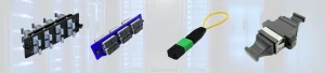


In modern data centers and high-density network environments, MPO/MTP fiber optic cables have become the backbone of connectivity infrastructure. These multi-fiber connectors enable faster deployment, reduced installation time, and higher port density compared to traditional duplex connectors. However, one critical aspect that often causes confusion and deployment challenges is fiber polarity.
Understanding MPO/MTP cable polarity is essential for network engineers, data center managers, and anyone involved in fiber optic infrastructure. Incorrect polarity can lead to link failures, network downtime, and costly troubleshooting. This comprehensive guide will walk you through everything you need to know about Type A, B, and C polarity methods.
What is MPO/MTP Cable Polarity?
Polarity in fiber optic cables refers to the direction of light transmission through the fiber strands. In any fiber connection, signals must travel from a transmitter (Tx) at one end to a receiver (Rx) at the opposite end. For proper communication, the transmit fiber from one device must connect to the receive fiber of another device.
In traditional duplex LC or SC connections, managing polarity is straightforward with just two fibers. However, MPO/MTP connectors typically house 12 or 24 fibers in a single connector, making polarity management significantly more complex. Each fiber position must be carefully mapped to ensure correct Tx-to-Rx alignment throughout the entire link.
Why Polarity Matters
Proper polarity ensures:
- Reliable network connectivity without signal path errors
- Reduced installation time through standardized methods
- Lower troubleshooting costs when issues arise
- Scalability for future network expansion
- Compliance with industry standards like TIA-568
Polarity errors are one of the most common causes of link failures in MPO/MTP deployments. Even a single incorrectly mapped fiber can prevent an entire channel from functioning.
The Three Standard Polarity Types
The telecommunications industry has established three standard polarity methods for MPO/MTP cable systems: Type A, Type B, and Type C. Each method defines how fibers are mapped from one connector end to the other, and each serves specific applications in network architecture.
Type A Polarity (Straight-Through)
Type A polarity uses a straight-through fiber mapping where position 1 on one end connects to position 1 on the other end, position 2 connects to position 2, and so on.
Key Characteristics:
- One end has a key-up connector, the other has a key-down connector
- Fiber mapping: 1→1, 2→2, 3→3… 12→12
- Creates a direct fiber path without crossover
- Requires additional components (like Type A-to-B conversion modules) to achieve proper Tx/Rx polarity
Typical Applications:
- Backbone trunk cables in structured cabling systems
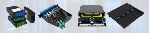
- Used with cassettes or breakout modules that provide polarity conversion
- Interconnect links between passive components
Type A cables are commonly used as trunk cables because they maintain consistent fiber positions, making them easier to test and trace. However, they require polarity-flipping components elsewhere in the link to achieve correct Tx-to-Rx alignment.

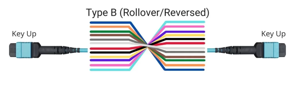
Type B Polarity (Reversed/Flipped)
Type B polarity features a complete flip of the fiber array. Position 1 on one end connects to position 12 on the other end, position 2 connects to position 11, and so on, creating a full reversal.
Key Characteristics:
- Key-up connectors on both ends
- Fiber mapping: 1→12, 2→11, 3→10… 12→1
- Built-in crossover within the cable itself
- Recommended by TIA-568 standard for data center backbone cabling
Typical Applications:
- Direct equipment-to-equipment connections
- Backbone trunk cables in data centers
- Links where polarity conversion happens at the connector level
Type B is often considered the most straightforward polarity method for data center deployments. Because the crossover occurs within the cable itself and both connectors use the same key orientation, it reduces the risk of incorrect insertion and simplifies inventory management. Many industry experts recommend standardizing on Type B for consistency.
Type C Polarity (Pairs Flipped)
Type C polarity flips adjacent fiber pairs. Position 1 connects to position 2, position 2 connects to position 1, position 3 connects to position 4, position 4 connects to position 3, and so on.
Key Characteristics:
- One end has a key-up connector, the other has a key-down connector
- Fiber mapping: 1→2, 2→1, 3→4, 4→3… 11→12, 12→11
- Each duplex pair is swapped
- Often used with specific breakout cable designs
Typical Applications:
- Breakout cables from MPO to duplex LC
- Certain patch cord configurations
- Systems requiring pair-level polarity management
Type C is less commonly used in backbone infrastructure but finds applications in specific breakout scenarios where pair-level control is needed.

How to Choose the Right Polarity Type
Selecting the appropriate polarity method depends on your network architecture, equipment configuration, and organizational standards. Here are key considerations:
Network Architecture Considerations
- Link Design: Understand your complete optical path from transceiver to transceiver, including all interconnects, patch panels, and cassettes.
- Component Compatibility: Ensure all components in your link (trunk cables, cassettes, patch cords) work together to maintain proper polarity.
- Transceiver Configuration: Know whether your optical transceivers use parallel optics and how they’re configured for Tx/Rx.
- Future Scalability: Choose a polarity method that supports easy expansion and reconfiguration.
Industry Recommendations
The TIA-568 standard recommends Type B polarity for data center backbone cabling due to its:
- Consistent implementation across different link configurations
- Reduced risk of insertion errors (both ends use the same key orientation)
- Simplified troubleshooting process
- Clear documentation and industry support
Standardization Benefits
Many organizations find it beneficial to standardize on a single polarity type across their entire infrastructure. This approach:
- Reduces complexity and potential for errors
- Simplifies inventory management
- Makes training and documentation easier
- Streamlines troubleshooting procedures

Polarity Validation and Testing
Ensuring correct polarity is critical during both manufacturing and installation. Several methods can verify that your MPO/MTP cables maintain proper polarity.
Visual Inspection
Before any testing, conduct a visual examination:
- Verify connector key positions (up or down)
- Check for physical damage or contamination
- Confirm proper cable labeling matches polarity type
- Inspect end-face cleanliness using a fiber microscope
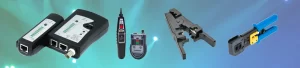
Testing Methods
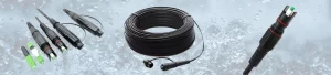
Visual Fault Locator (VFL): A VFL injects visible red light into specific fiber positions, allowing you to trace the light path and verify which positions connect to which endpoints. This simple tool is invaluable for quick polarity verification during installation.
Optical Power Meter and Light Source: By injecting a calibrated light signal at one end and measuring received power at the other end, you can verify both polarity and optical loss. Testing should be performed on all fiber positions to ensure complete link integrity.
Professional MPO Polarity Test Kits: Specialized test equipment designed for MPO connectors can automatically verify polarity type and identify any fiber mapping errors. These kits are essential for large deployments where manual testing would be time-consuming.
Conclusion
Understanding MPO/MTP cable polarity is essential for successful fiber optic network deployment. The three standard polarity types – Type A, B, and C – each serve specific purposes, with Type B generally recommended for its consistency and ease of implementation.
Key takeaways:
- Type A (straight-through) maintains fiber positions and requires external polarity conversion
- Type B (reversed) provides built-in crossover and is recommended by industry standards
- Type C (pairs flipped) swaps adjacent pairs and is useful for specific breakout applications
- Standardization on a single polarity type simplifies deployment and maintenance
- Proper testing during installation prevents costly troubleshooting later
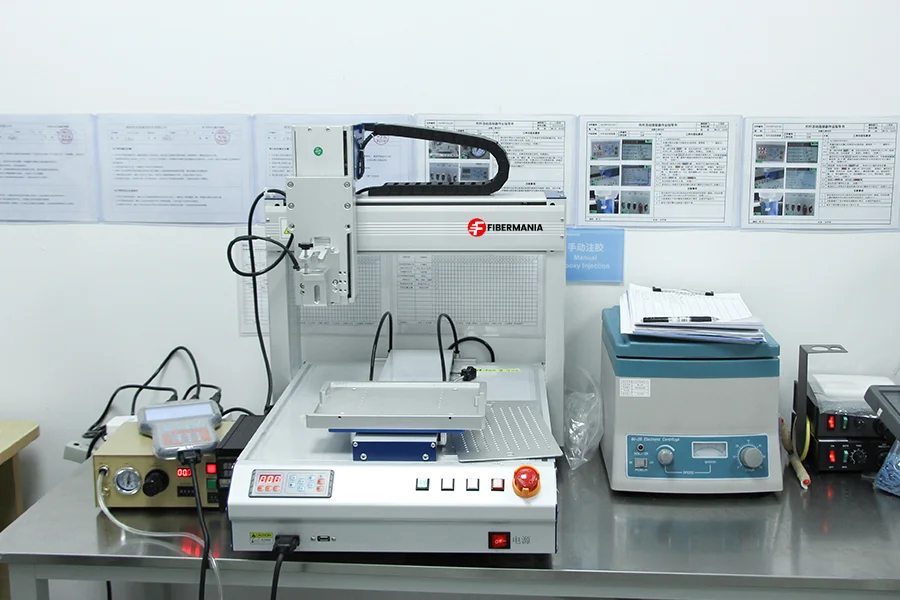
As fiber optic infrastructure becomes increasingly dense and complex, working with a reliable manufacturing partner becomes critical. FiberMania’s OEM capabilities ensure you receive precisely configured MPO/MTP cables that meet your exact polarity requirements, backed by rigorous testing and quality control.
Whether you’re deploying a new data center, upgrading existing infrastructure, or managing ongoing network expansion, understanding and implementing correct polarity is fundamental to success. With proper planning, testing, and reliable manufacturing partners, MPO/MTP deployments can provide the high-density, high-performance connectivity modern networks demand.