Skip to content































In modern high‑speed optical networks, reliable testing is just as critical as high‑performance transmission. As data rates scale from 40G and 100G to 400G, 800G, and beyond, multi‑fiber interfaces such as MPO and MTP have become the backbone of data centers, cloud infrastructure, and telecom networks. In this environment, MPO/MTP loopback adapters play a vital role in validating optical transceivers, switch ports, and network equipment before and after deployment.
An MPO/MTP loopback adapter provides a simple yet powerful method to verify that optical signals can be transmitted and received correctly by a device. By looping the transmitted signal back to the receiver within a single connector, engineers can quickly determine whether a port or transceiver is functioning as designed—without the need for a full end‑to‑end fiber link.
This article explores how MPO/MTP loopback adapters work, their internal structure, polarity configurations, testing scenarios, and why they are essential tools in professional optical network testing.

What Is a Fiber Optic Loopback Adapter?
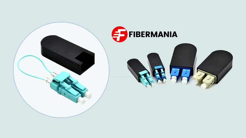
A fiber optic loopback adapter is a passive testing component used to route an optical signal from a transmitter (Tx) back to a receiver (Rx). It does not modify, amplify, or regenerate the signal. Instead, it creates a closed optical path that allows network equipment to test its own transmission and reception capabilities.
Loopback adapters are commonly used for:
Verifying optical transceiver functionality
Testing switch, router, and NIC ports
Diagnosing link failures or abnormal performance
Factory acceptance testing (FAT) and field commissioning
Maintenance and troubleshooting in live or lab environments
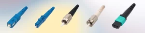
Fiber loopback adapters are available in multiple connector formats, including SC, LC, FC, E2000, MTRJ, and—most importantly for high‑density systems—MPO and MTP.
Understanding MPO and MTP Interfaces
MPO (Multi‑Fiber Push‑On) and MTP (Mechanical Transfer Push‑On) connectors are multi‑fiber interfaces designed to terminate ribbon fiber cables containing 8, 12, 16, 24, or more fibers in a single compact connector.
MPO is an IEC‑standardized connector interface.
MTP is a high‑performance MPO‑compatible connector developed by US Conec, featuring improved mechanical design, better fiber alignment, and lower insertion loss.
These connectors are widely used in parallel‑optics applications, such as SR4, SR8, DR4, and FR4 transceiver architectures, where multiple fibers simultaneously transmit and receive data.
Because a single MPO/MTP connector may carry multiple transmit and receive channels, loopback testing in these systems requires careful internal fiber mapping and polarity control.
How an MPO/MTP Loopback Adapter Works
An MPO/MTP loopback adapter contains a short length of multi‑fiber ribbon internally. Both ends of this fiber ribbon are terminated into the same MPO or MTP connector housing. Inside the adapter, specific fiber channels are paired so that transmitted signals are directly returned to their corresponding receive channels.
In operation:
The network device or transceiver sends optical signals through its transmit fibers.
Inside the loopback adapter, these transmit fibers are internally connected to designated receive fibers.
The signal is reflected back to the receiving side of the same port.
The device detects the returned signal and verifies proper transmission, alignment, and reception.
This closed‑loop configuration enables fast validation of optical ports without external patch cords, remote devices, or additional test equipment.
Importantly, an MPO/MTP loopback adapter does not alter the optical signal. It simply returns the signal to its source, preserving the original wavelength, power level, and modulation characteristics.

Polarity and Channel Alignment in MPO/MTP Loopbacks
Polarity management is one of the most critical aspects of MPO/MTP loopback design. Polarity defines how transmit fibers align with receive fibers to ensure correct signal flow.
Different fiber counts require different internal channel‑pairing schemes:
8‑Fiber MPO/MTP Loopback
In many 8‑fiber loopback designs, fibers are paired symmetrically across the connector. For example:
Fiber 1 ↔ Fiber 8
Fiber 2 ↔ Fiber 7
Fiber 3 ↔ Fiber 6
Fiber 4 ↔ Fiber 5
Some designs may leave the middle channels unused, depending on the application and transceiver architecture. This configuration is commonly used for 40G SR4 and certain 100G applications.
12‑Fiber MPO/MTP Loopback
In 12‑fiber loopbacks, only 8 fibers may be actively used for transmission, while the remaining fibers are reserved or left dark. The loopback internally pairs the active Tx/Rx channels according to the transceiver’s lane definition.
16‑Fiber and Higher‑Density Loopbacks
With the rise of 400G and 800G optics, 16‑fiber and 24‑fiber MPO/MTP loopback adapters are increasingly common. These require highly precise internal routing to ensure correct lane‑to‑lane alignment and compliance with IEEE and MSA standards.
Proper polarity design ensures that each transmit lane is looped back to its intended receive lane, allowing accurate performance validation.
Key Applications of MPO/MTP Loopback Adapters
1. Transceiver Functional Testing
MPO/MTP loopback adapters are widely used to confirm that optical transceivers are operating correctly. By inserting a loopback adapter into a transceiver port, engineers can quickly determine whether the module can transmit and receive signals within expected parameters.
2. Switch and Router Port Verification
Before deploying switches or routers into production networks, technicians often perform loopback tests to validate port integrity. This helps identify defective ports early, reducing downtime and troubleshooting costs.
3. Data Center Commissioning
During data center build‑outs, MPO/MTP loopbacks enable rapid validation of high‑density ports without waiting for full fiber links to be installed. This accelerates commissioning and acceptance testing.
4. Troubleshooting and Maintenance
When a link failure occurs, a loopback adapter can isolate whether the issue originates from the transceiver, the port, or the cabling infrastructure. This targeted testing significantly shortens mean time to repair (MTTR).
Advantages of MPO/MTP Loopback Testing
MPO/MTP loopback adapters offer several key advantages:
Speed: Immediate testing without external equipment
Simplicity: Plug‑and‑play operation
Accuracy: Direct verification of Tx/Rx functionality
Cost efficiency: Reduces the need for full test links
Scalability: Supports high‑fiber‑count and high‑speed interfaces
These benefits make MPO/MTP loopbacks indispensable tools for both laboratory and field environments.
Quality Considerations and Best Practices
For reliable test results, MPO/MTP loopback adapters must be manufactured with high precision and strict quality control. Key factors include:
Accurate fiber alignment and polishing
Low insertion loss and high return loss
Correct polarity and channel mapping
Clean, contamination‑free end faces
Compliance with relevant IEC and TIA standards
Using poorly manufactured loopbacks can lead to false test results, misdiagnosis, and unnecessary equipment replacement.
Conclusion
MPO/MTP loopback adapters are essential tools in today’s high‑speed optical networks. By providing a controlled and efficient method to loop transmitted signals back to their source, they enable accurate validation of transceivers, ports, and network equipment.
As data rates and fiber densities continue to increase, the importance of correct polarity management, precise internal routing, and high manufacturing quality becomes even greater. Whether used in data centers, telecom networks, or testing laboratories, MPO/MTP loopback adapters remain a fundamental component for ensuring reliable optical performance.
At FiberMania, we design and manufacture MPO/MTP loopback adapters with strict quality control and flexible customization options to support a wide range of testing and deployment scenarios.