Skip to content


















Fiber optic connectors are essential components in modern optical communication systems, and their performance depends heavily on the precision of their internal structures. Among these components, the ferrule plays a particularly important role. Although it is a relatively small part of a connector, its dimensional accuracy, material properties, and endface geometry directly influence fiber alignment, insertion loss (IL), and return loss (RL).
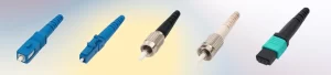
Different connector applications require different ferrule materials and manufacturing approaches. Zirconia ceramic ferrules are widely used in single-fiber connectors such as SC and LC, while metal ferrules remain suitable for certain ruggedized applications. In multi-fiber connectivity systems such as MPO/MTP, precision-molded polymer ferrules provide an entirely different alignment solution.
Understanding these differences is important when selecting fiber optic patch cords, pigtails, and high-density cabling assemblies. This article explores how fiber optic ferrules work, compares the major ferrule materials, explains critical dimensional tolerances, and examines how ferrule quality affects overall optical performance.
1. What Is a Fiber Optic Connector Ferrule?
A fiber optic ferrule is a precision-engineered component inside a fiber optic connector that holds and aligns the optical fiber. It is typically located at the front end of the connector, where it establishes the physical interface between two mating fibers.
Unlike the connector housing, which provides mechanical protection and connection stability, the ferrule directly determines the positioning of the optical fiber. Its two primary functions are maintaining accurate fiber alignment and providing a precisely polished mating surface.
Fiber Alignment and Positioning
A standard single-mode optical fiber has a nominal cladding diameter of 125 µm, while its optical core is only approximately 9 µm in diameter. This means that even a small alignment deviation can cause a significant portion of the optical signal to be lost when two fibers are connected.
The ferrule contains a precision-machined or precision-formed central bore that holds the stripped optical fiber. The position of this bore relative to the ferrule’s outer diameter determines how accurately the fiber core aligns with the connector’s optical axis.
Providing a Physical Contact Surface
The second function of a ferrule is to establish a reliable physical connection between two optical fibers. Its endface is polished into a controlled geometry, typically with a slightly convex surface, allowing the fiber ends to make physical contact under spring pressure.
Proper endface geometry minimizes air gaps, reduces unwanted reflections, and helps maintain stable optical transmission. Any deviation in the polished surface can negatively affect insertion loss and return loss.
Key Ferrule Dimensions
Several dimensional parameters determine ferrule performance:
| Parameter | Function | Typical Specification |
|---|---|---|
| Inner Diameter (ID) | Holds and positions the optical fiber | Approximately 125 µm |
| Concentricity | Controls bore alignment relative to the outer diameter | ≤1.0 µm to ≤0.3 µm |
| Outer Diameter (OD) | Fits the connector alignment sleeve | 2.5 mm or 1.25 mm |
| Radius of Curvature (ROC) | Defines the curvature of the polished endface | 5–30 mm |
| Apex Offset | Measures the displacement between the fiber center and polishing apex | Typically ≤50 µm |
| Fiber Height | Measures fiber protrusion or undercut relative to the polished surface | Nanometer-level control |
The outer diameter also determines the ferrule family used in different connector designs. For example, SC and FC connectors typically use 2.5 mm ferrules, while LC and MU connectors use 1.25 mm ferrules. These components are not interchangeable because they require different alignment sleeves and connector interfaces.
2. Zirconia vs. Metal vs. Polymer: Which Ferrule Material Is Best?
Ferrule materials are selected according to the optical precision, mechanical durability, and environmental conditions required by the application. No single material is ideal for every connector design.
Zirconia Ceramic Ferrules
Zirconia ceramic (ZrO₂) is the most widely used material for single-fiber optical connector ferrules. Its popularity comes from its excellent dimensional stability, hardness, wear resistance, and ability to achieve highly polished endfaces.
Zirconia ferrules are commonly manufactured through precision molding followed by machining and finishing processes. This manufacturing approach allows tight control over the central bore, concentricity, and external dimensions.
Their hardness also helps maintain endface quality over repeated mating cycles. This is particularly important in applications where connectors are frequently connected, disconnected, and cleaned.
Typical applications include:
-
SC, LC, FC, and ST fiber optic connectors.
-
Single-mode and multimode fiber patch cords.
-
Fiber optic pigtails and adapter assemblies.
-
Data center and telecommunications connectivity.
For applications with demanding insertion loss and return loss requirements, zirconia ceramic is generally the preferred ferrule material.
Metal Ferrules
Metal ferrules, commonly manufactured from stainless steel or specialty alloys, are designed primarily for mechanical durability.
Compared with ceramic, metal offers greater resistance to impact, vibration, and certain forms of mechanical abuse. These properties make metal ferrules suitable for some industrial, instrumentation, and ruggedized optical connection systems.
However, metal ferrules present challenges when extremely precise optical alignment is required. Achieving the same sub-micron bore accuracy and mirror-like polishing quality can be more difficult.
Another consideration is thermal expansion. Metal, glass fiber, and bonding adhesives have different expansion characteristics. Under temperature fluctuations, these differences can cause stress at the fiber-to-ferrule interface, potentially resulting in fiber movement or bonding failure.
Metal ferrules are therefore more appropriate when mechanical robustness is the primary requirement rather than achieving the lowest possible optical loss.
Polymer Ferrules
Polymer ferrules provide a different approach to fiber alignment, particularly in multi-fiber connector systems.
They are commonly manufactured from glass-filled engineering plastics, such as polyphenylene sulfide (PPS), which provide dimensional stability and relatively low moisture absorption.
Unlike single-fiber ceramic ferrules, polymer ferrules can accommodate multiple optical fibers within a single precision-molded structure. This makes them suitable for high-density optical connectivity.
Their most important application is the MT ferrule used in MPO/MTP connectors. Instead of relying on an individual alignment sleeve for each fiber, MT ferrules use precision guide holes and alignment pins to position multiple fibers simultaneously.
Ferrule Material Comparison
| Material | Main Advantages | Limitations | Typical Applications |
|---|---|---|---|
| Zirconia Ceramic | High precision, excellent hardness, superior polishability | More brittle than metal | SC, LC, FC, ST |
| Stainless Steel / Metal | Mechanical strength, impact and vibration resistance | More challenging optical precision and polishing | Ruggedized and industrial connectors |
| Glass-Filled Polymer | Multi-fiber molding capability, dimensional stability | Requires careful endface protection and cleaning | MPO/MTP connectors |
The most suitable ferrule material depends on the connector architecture. Zirconia is preferred for precision single-fiber alignment, while glass-filled polymer is the established solution for multi-fiber MT interfaces.
3. Why Ferrule Tolerances Matter for Optical Performance
The material of a ferrule is only one part of its performance. Its dimensional tolerances determine how accurately the optical fiber is positioned and how consistently two connectors can mate.
Even when two connectors use the same ferrule material and connector design, differences in manufacturing precision can produce measurable variations in optical performance.
Three parameters deserve particular attention: bore diameter, concentricity, and outer diameter.
Inner Diameter and Fiber Fit
The ferrule’s inner diameter must accommodate the optical fiber’s glass cladding while maintaining sufficiently accurate positioning.
A standard single-mode fiber has a nominal cladding diameter of 125 µm, but its actual diameter varies within the manufacturer’s specified tolerance. Therefore, the ferrule bore must provide an appropriate balance between clearance and alignment accuracy.
If the bore is too large, the fiber may move laterally within the ferrule, increasing alignment errors. If the bore is too small, the fiber may be difficult to insert, increasing manufacturing rejection rates and potentially damaging the glass.
For this reason, ferrule manufacturers must control the bore diameter within a carefully defined tolerance range rather than relying on a nominal dimension alone.
Concentricity and Fiber Alignment
Concentricity describes the alignment between the ferrule’s inner bore and its outer diameter. It is one of the most important parameters affecting the optical performance of single-fiber connectors.
If the bore is not perfectly centered, the optical fiber will also be displaced from the connector’s mechanical axis. When two connectors are mated, this displacement can result in lateral misalignment between their optical cores.
Typical ferrule concentricity grades include:
-
Standard grade: ≤1.0 µm.
-
Premium grade: approximately ≤0.5 µm.
-
Low-loss grade: approximately ≤0.3 µm.
A smaller concentricity value generally indicates more precise fiber positioning and better potential for low insertion loss.
This becomes particularly important in single-mode applications, where the optical core is extremely small. Even a few micrometers of lateral misalignment can produce substantial signal attenuation.
Outer Diameter and Mechanical Compatibility
The ferrule’s outer diameter determines how it fits into the connector’s alignment sleeve. During mating, the sleeve positions two ferrules along a common axis, helping maintain consistent fiber alignment.
Common ferrule sizes include 2.5 mm for SC and FC connectors and 1.25 mm for LC connectors.
Manufacturing deviations in outer diameter, roundness, or surface finish can affect the mechanical fit and alignment stability of the connector. Therefore, accurate control of both inner and outer dimensions is necessary for reliable performance.
4. Endface Geometry: How Ferrule Polishing Affects IL and RL
Even when a ferrule has excellent dimensional accuracy, its optical performance can still be compromised by poor endface geometry.
The polished endface determines how two optical fibers physically contact each other. Three measurements are particularly important: radius of curvature, apex offset, and fiber height.
Radius of Curvature (ROC)
Radius of curvature describes the curvature of the polished ferrule endface.
A controlled convex surface helps concentrate contact pressure around the fiber interface, allowing two mated fibers to establish reliable physical contact.
If the curvature is too flat or too steep, the contact condition may become inconsistent, potentially increasing insertion loss and unwanted reflections.
For many single-mode PC and UPC ferrules, a typical radius of curvature specification falls within approximately 5–30 mm, depending on the connector interface and applicable requirements.
Apex Offset
Apex offset measures the distance between the center of the optical fiber and the highest point of the polished ferrule surface.
Ideally, the polishing apex should be positioned close to the fiber center. Excessive offset can cause uneven contact pressure and affect the physical connection between two mated fibers.
A commonly used maximum apex offset is 50 µm.
Fiber Height: Protrusion and Undercut
Fiber height describes the position of the optical fiber relative to the ferrule’s polished surface.
There are two conditions to consider:
-
Fiber Protrusion: The fiber extends beyond the surrounding polished surface.
-
Fiber Undercut: The fiber sits slightly below the surrounding ferrule surface.
Excessive protrusion can make the glass fiber vulnerable to damage during mating. Excessive undercut may prevent two fibers from making proper physical contact, increasing optical reflections and potentially affecting insertion loss.
These parameters must be controlled together with the radius of curvature and apex offset to achieve consistent connector performance.
UPC vs. APC: Different Polishing Requirements
The polishing angle also determines the optical characteristics of a connector.
UPC (Ultra Physical Contact) connectors have a polished convex endface without an intentional angled interface. They are commonly used in data center equipment, optical transceivers, and general-purpose fiber connections.
APC (Angled Physical Contact) connectors feature an angled endface, typically at 8 degrees. This angled surface directs reflected light away from the optical source, resulting in lower back reflection.
Typical return loss specifications are:
| Connector Polish | Endface Design | Typical Return Loss |
|---|---|---|
| PC | Convex physical contact | ≥40 dB |
| UPC | Ultra-polished physical contact | ≥50 dB |
| APC | Angled physical contact | ≥60 dB |
The appropriate polish type depends on the application and equipment interface. UPC and APC connectors should not be directly mated because their different endface geometries can cause poor contact and damage.
5. How Ferrule Quality Determines Insertion Loss and Return Loss
Insertion loss and return loss are two fundamental indicators of fiber optic connector performance.
Insertion loss measures the amount of optical power lost when a signal passes through a connection. Return loss measures how much optical power is reflected back toward the source.
Ferrule quality affects both parameters through fiber alignment and endface contact.
The Relationship Between Ferrule Precision and Insertion Loss
When two connectors are mated, their optical cores must be accurately aligned to maximize signal transfer.
Poor concentricity, excessive bore clearance, and inaccurate fiber positioning can create lateral misalignment. This prevents part of the transmitted optical signal from entering the receiving fiber.
The higher the misalignment, the greater the potential insertion loss.
For example, two connectors with standard-grade ferrules may produce higher loss variations when randomly mated than connectors manufactured with tighter concentricity tolerances.
This is why ferrule quality is especially important in single-mode fiber applications, high-speed data transmission, and optical links with limited power budgets.
The Relationship Between Endface Quality and Return Loss
Return loss is strongly influenced by the physical contact condition and surface quality of the connector endface.
An air gap between two fibers can create a refractive index discontinuity, causing a portion of the optical signal to reflect back toward the source.
Poor polishing, contamination, excessive fiber undercut, and incorrect apex positioning can all contribute to increased reflections.
APC polishing helps reduce these reflections by directing reflected light away from the optical source.
Understanding Connector Insertion Loss Grades
Connector performance is commonly classified according to insertion loss requirements under defined testing conditions.
The following values illustrate commonly referenced single-mode random-mating performance categories:
| Grade | Mean Insertion Loss | Maximum IL for More Than 97% of Samples |
|---|---|---|
| Grade A (proposed) | ≤0.07 dB | ≤0.15 dB |
| Grade B | ≤0.12 dB | ≤0.25 dB |
| Grade C | ≤0.25 dB | ≤0.50 dB |
| Grade D | ≤0.50 dB | ≤1.00 dB |
These grades describe connector-level performance rather than ferrule material alone. Achieving consistent low-loss performance requires appropriate ferrule tolerances, fiber quality, termination processes, and endface polishing.
A connector cannot reliably achieve a demanding random-mating performance target simply because it uses zirconia ceramic. The dimensional accuracy of the ferrule and the consistency of the complete manufacturing process are equally important.
6. Why MPO/MTP Connectors Use Polymer Ferrules
Single-fiber connectors such as LC and SC typically use individual ceramic ferrules. However, high-density data center applications often require multiple optical fibers to be connected simultaneously.
This is where MPO/MTP connectivity uses a different ferrule design: the MT ferrule.
MT ferrules are generally manufactured from glass-filled polymer and feature multiple precision fiber holes arranged in a rectangular structure. Instead of using an alignment sleeve around each individual fiber, the connector relies on guide pins and precision guide holes to align the entire fiber array.
How MT Ferrules Work
A typical MPO connector uses two MT ferrules:
-
Male connector: Contains two guide pins.
-
Female connector: Contains corresponding guide-pin holes.
When the connectors are mated, the guide pins engage with the holes, positioning the two fiber arrays accurately.
This design allows multiple fibers to be connected within a single compact interface, making MPO/MTP connectors suitable for high-density data center cabling.
Why Polymer Is Suitable for Multi-Fiber Connectivity
The precision of an MT ferrule comes primarily from its molding process and the accurate positioning of its fiber holes.
Glass-filled polymer provides dimensional stability and allows manufacturers to produce multiple fiber positions in a single component. This is more practical than individually manufacturing and assembling ceramic ferrules for every fiber in a multi-fiber array.
However, MT ferrules have their own quality requirements. Fiber-hole positioning, guide-pin accuracy, endface flatness, and cleanliness are critical to maintaining consistent optical performance.
A small amount of contamination on an MPO endface can affect multiple optical channels simultaneously. Therefore, endface inspection and cleaning are especially important for high-density MPO/MTP connections.
7. Common Ferrule Problems and Their Impact on Fiber Optic Connections
Ferrule-related defects do not always result in immediate connection failure. Some problems appear as unstable optical performance, increasing insertion loss, or intermittent signal interruptions after repeated mating.
The following table summarizes several common issues and their potential causes.
| Observed Problem | Possible Ferrule-Related Cause | Recommended Inspection |
|---|---|---|
| Increasing insertion loss after repeated mating | Fiber pushback or adhesive bonding failure | Check fiber position and bonding process |
| Consistently higher loss on individual connectors | Poor concentricity or core misalignment | Verify ferrule concentricity |
| High reflectance despite acceptable insertion loss | Incorrect endface geometry or excessive undercut | Inspect ROC, apex offset, and fiber height |
| Intermittent signal loss when moving the cable | Cracked or chipped ferrule | Inspect the ferrule endface under magnification |
| Loss remains high after cleaning | Polishing defects or contamination trapped near the fiber | Perform endface inspection and polishing-process checks |
These problems demonstrate why connector quality cannot be evaluated through visual appearance alone. Dimensional inspection, endface measurement, and optical performance testing are all necessary to verify ferrule quality.
8. How to Evaluate Ferrule Quality During Manufacturing and Inspection
For fiber optic connector manufacturers and buyers, ferrule specifications should be clearly defined before production. Relying only on material descriptions or general quality claims does not provide sufficient assurance of optical performance.
Several factors should be considered during supplier evaluation and incoming inspection.
Define the Ferrule Material and Connector Interface
Specify the required ferrule material according to the connector application. Zirconia ceramic is generally appropriate for SC, LC, FC, and other single-fiber interfaces, while glass-filled polymer is used for MT-based MPO/MTP systems.
The ferrule diameter and connector interface must also be clearly defined to ensure compatibility with the corresponding alignment sleeve and connector components.
Specify Bore Diameter and Concentricity
The inner diameter should be specified as an acceptable range rather than a nominal value alone. Concentricity should also be defined with a maximum tolerance appropriate to the required connector insertion loss grade.
For low-loss single-mode assemblies, tighter concentricity requirements can help improve random-mating consistency.
Control Endface Geometry
Endface inspection should evaluate radius of curvature, apex offset, and fiber height. These parameters are important for ensuring reliable physical contact and controlling optical reflections.
Three-dimensional interferometry is commonly used to measure endface geometry with high precision.
Perform Optical and Mechanical Testing
Ferrule inspection should be integrated into a broader connector quality-control process. Relevant tests include:
-
Insertion loss and return loss testing.
-
Endface geometry inspection.
-
Ferrule dimensional and concentricity verification.
-
Mating and extraction force testing.
-
Repeated mating-cycle evaluation.
-
Visual inspection for scratches, chips, and contamination.
For MPO/MTP assemblies, additional attention should be given to guide-pin positioning, fiber-hole alignment, polarity, and multi-channel optical performance.
A consistent inspection process helps identify manufacturing deviations before connectors are integrated into larger fiber optic assemblies.
Conclusion
The ferrule is one of the most important components in a fiber optic connector because it directly determines fiber alignment and the quality of the mating interface. Its material, bore diameter, concentricity, and endface geometry all influence insertion loss, return loss, and long-term connection reliability.
Zirconia ceramic remains the preferred choice for precision single-fiber connectors, while metal ferrules serve applications requiring greater mechanical durability. For high-density multi-fiber connectivity, glass-filled polymer MT ferrules provide an effective solution through precision-molded fiber arrays and guide-pin alignment.
For fiber optic manufacturers, system integrators, and data center operators, understanding ferrule specifications is essential when selecting connectors and evaluating cable assembly quality. A reliable optical connection is not determined by material alone, but by the combined precision of the ferrule, fiber termination, polishing process, and final inspection.
At FiberMania, we focus on fiber optic connectivity solutions for telecommunications and data center applications, including SC, LC, MPO/MTP connectors, fiber optic patch cords, pigtails, and customized cable assemblies. Consistent manufacturing processes and comprehensive product testing help support reliable optical connections across different network environments.